Rosette Transformation Analysis Object *
With this analysis object, you can use a strain gauge rosette to calculates various quantities, such as principal stresses or principal strains.
A strain gauge rosette is an array of two or more closely spaced strain gauge grids of different orientations for measuring the normal strains on the underlying surface of a test object. In the case of a biaxial stress state whose principal directions are unknown, three independent strain measurements in different directions are sufficient to determine the principal strains and principal stresses.
Rosette Properties
Calculation for the following rosette types is possible:
Description |
Description |
|---|---|
T rosette |
Two perpendicular grids; position a and b |
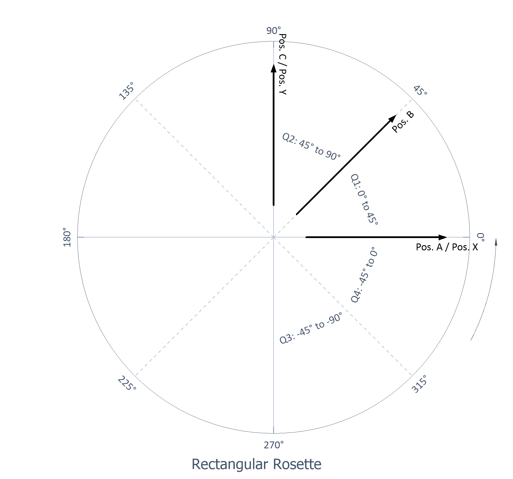
Rectangular rosette |
Three grids, with 45° between grids |
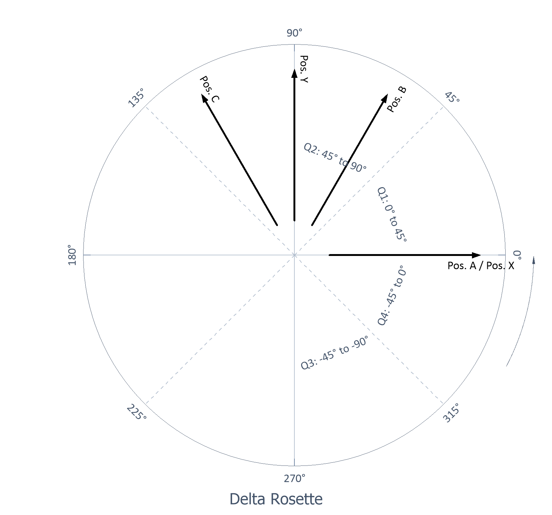
Delta rosette |
Three grids, with second and third grids spaced at 60° and 120° |
If the test object material is homogeneous in composition, behaves isotropically, and exhibits a linear stress-strain relationship, then Hook's law for the biaxial stress state can be applied to calculate the principal stresses from the principal strains. Knowledge of the Modulus of elasticity E (Young’s modulus) and Poisson’s ratio of the material to be measured is required [1, 2].
Transverse sensitivity
The term transverse sensitivity, or transverse strain sensitivity, refers to the response of strain gauges when strains are applied to them transverse to the grid longitudinal axis. Ideally, it is desirable for strain gauges to be completely insensitive to such transverse strains. In practice, however, most strain gauges are sensitive to transverse strain to some degree. Fortunately, the transverse sensitivity of modern film strain gauges is very low, on the order of a few percentage points of the strain sensitivity in the grid direction. The magnitude of the transverse strain sensitivity depends on the grid alloy and grid geometry.
A mathematical correction can be made by specifying the transverse sensitivity [3]. With the analysis object, the corrected strain signals can be output and thus compared with the measured strain signals.
Temperature compensation
Optionally, temperature compensation can be performed for the measured strain signals. Here it is assumed that the strain gauges are self-compensated, i.e. the influence of the cable resistance has already been eliminated. The temperature influence of strain gauge connection ribbon is also not taken into account. The residual error is determined by a polynomial function specified in the strain gauge data sheet. In addition to the polynomial function, the formula used includes terms for the temperature dependency of the gauge factor and additional consideration of a deviation between the thermal expansion coefficient of the material on which the measurement was performed and the thermal expansion coefficient of the strain gauge grid material [4, 5].
The polynomial coefficients are specified as a data series. The first value corresponds to coefficient a0, the second value corresponds to coefficient a1, etc.
The following formula is used for temperature compensation:
Description |
Symbol |
|
|---|---|---|
Strain data set |
εu(T) |
|
Temperature data set |
T |
|
Polynomial coefficients |
a0, a1, a2, ... |
|
Reference temperature |
TRef |
|
Gauge factor |
kD |
|
Material expansion coefficient |
αM |
|
Temperature coefficient of gauge factor |
αk |
|
Strain gauge expansion coefficient |
αSG |
Output options
The following output options are available:
Designation |
Description |
|
|---|---|---|
Principal strain 1 |
Principal strain 1 |
|
Principal strain 2 |
Principal strain 2 |
|
Principal stress 1 |
Stress in direction of principal strain 1 |
|
Principal stress 2 |
Stress in direction of principal strain 2 |
|
Angle |
Angle |
|
Shear strain |
Shear strain |
|
Shear stress |
Stress in the direction of shear strain |
|
Equivalent von Mises stress |
Equivalent von Mises stress |
|
Strain X |
Corresponds to the corrected strain at position a. |
|
Strain Y |
Corresponds to the 90° counterclockwise displaced strain at position a. |
|
Stress X |
Stress in the direction of strain X |
|
Stress Y |
Stress in the direction of strain Y |
|
Corrected strain at position a |
Strain corrected at position a with the help of transverse sensitivity |
|
Corrected strain at position b |
Strain at position b corrected with the help of transverse sensitivity |
|
Corrected strain at position c |
Strain at position c corrected with the help of transverse sensitivity |
Calculation formulas
T rosette:
Designation |
Formula |
|
|---|---|---|
Principal strain 1 |
||
Principal strain 2 |
||
Principal stress 1 |
||
Principal stress 2 |
||
Angle |
90° |
|
Shear strain |
0 |
|
Shear stress |
||
Equivalent von Mises stress |
||
Strain X |
Corresponds to principal strain 1 |
|
Strain Y |
Corresponds to principal strain 2 |
|
Stress X |
Corresponds to principal stress 1 |
|
Stress Y |
Corresponds to principal stress 2 |
|
Corrected strain at position a, position b |
Rectangular rosette:
Designation |
Formula |
|
|---|---|---|
Principal strain 1 |
||
Principal strain 2 |
||
Principal stress 1 |
||
Principal stress 2 |
||
Angle |
||
Shear strain |
||
Shear stress |
||
Equivalent von Mises stress |
||
Strain X |
||
Strain Y |
||
Stress X |
||
Stress Y |
||
Corrected strain at position a, position b |
Delta rosette:
Designation |
Formula |
|
|---|---|---|
Principal strain 1 |
||
Principal strain 2 |
||
Principal stress 1 |
||
Principal stress 2 |
||
Angle |
||
Shear strain |
||
Shear stress |
||
Equivalent von Mises stress |
||
Strain X |
||
Strain Y |
||
Stress X |
||
Stress Y |
||
Corrected strain at position a, position b |
with


References
[1] Micro-Measurements. Tech Note TN-515: Strain Gage Rosettes: Selection, Application and Data Reduction.Document Number: 11065, Revision 14-Aug-2014.
[2] Karl Hoffmann. An Introduction to Stress Analysis using Strain Gauges. www.hbm.com
[3] Micro-Measurements. Tech Note TN-509: Errors Due to Transverse Sensitivity in Strain Gages.Document Number: 11059, Revision 28-Jun-2011.
[4] Hottinger Baldwin Messtechnik GmbH. Technical Information T05414_01_E00_01: Temperature compensation of strain gauge ¼-bridges – Clear, brief and understandable
[5] Micro-Measurements. Tech Note TN-504-1: Strain Gage Thermal Output and Gage Factor Variation with Temperature.Document Number: 11054, Revision 14-Aug-2014.
FPScript Functions Used
StrainGaugeTemperatureCompensation
* This analysis object is not available in FlexPro View and FlexPro Basic.
You might be interested in these articles
You are currently viewing a placeholder content from Facebook. To access the actual content, click the button below. Please note that doing so will share data with third-party providers.
More InformationYou need to load content from reCAPTCHA to submit the form. Please note that doing so will share data with third-party providers.
More InformationYou are currently viewing a placeholder content from Instagram. To access the actual content, click the button below. Please note that doing so will share data with third-party providers.
More InformationYou are currently viewing a placeholder content from X. To access the actual content, click the button below. Please note that doing so will share data with third-party providers.
More Information